- 您现在的位置:买卖IC网 > Sheet目录1994 > DS21Q58L (Maxim Integrated Products)IC TXRX E1 QUAD 3.3V 100-LQFP
DS21Q58 E1 Quad Transceiver
18 of 74
8.1 Power-Up Sequence
On power-up and after the supplies are stable, the DS21Q58 should be configured for operation by writing to all the
internal registers (this includes setting the test register to 00h) since the contents of the internal registers cannot be
predicted on power-up. The LIRST (CCR5.4) should be toggled from 0 to 1 to reset the line interface circuitry. (It
takes the device about 40ms to recover from the LIRST bit being toggled.) After the SYSCLK input is stable, the
ESR bits (CCR4.5 and CCR4.6) should be toggled from 0 to 1 (this step can be skipped if the elastic store is
disabled).
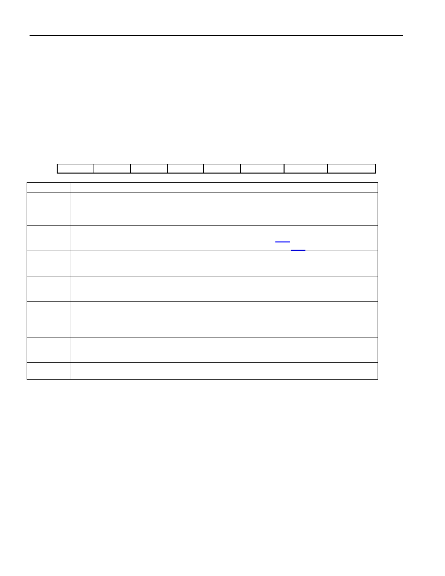
Register Name:
RCR
Register Description:
Receive Control Register
Register Address:
10 Hex
Bit #
7
6
5
4
3
2
1
0
Name
RSMF
RSM
RSIO
RESE
—
FRC
SYNCE
RESYNC
NAME
BIT
FUNCTION
RSMF
7
RSYNC Multiframe Function. Only used if the RSYNC pin is programmed in the
multiframe mode (RCR.6 = 1).
0 = RSYNC outputs CAS multiframe boundaries.
1 = RSYNC outputs CRC4 multiframe boundaries.
RSM
6
RSYNC Mode Select
0 = frame mode (see the timing diagrams in Section 24.1)
1 = multiframe mode (see the timing diagrams in Section 24.1)
RSIO
5
RSYNC I/O Select. (Note: This bit must be set to 0 when RCR .4 = 0.)
0 = RSYNC is an output (depends on RCR.6)
1 = RSYNC is an input (only valid if elastic store enabled)
RESE
4
Receive Elastic Store Enable
0 = elastic store is bypassed
1 = elastic store is enabled
—
3
Unused. Should be set = 0 for proper operation.
FRC
2
Frame Resync Criteria
0 = resync if FAS received in error three consecutive times
1 = resync if FAS or bit 2 of non-FAS is received in error three consecutive times
SYNCE
1
Sync Enable
0 = auto resync enabled
1 = auto resync disabled
RESYNC
0
Resync. When toggled from low to high, a resync is initiated. Must be cleared and
set again for a subsequent resync.
发布紧急采购,3分钟左右您将得到回复。
相关PDF资料
DS2404B
IC ECONORAM TIMECHIP 5.5V 16SSOP
DS2415P+T&R
IC TIME CHIP 1-WIRE 6-TSOC
DS2417X/T&R
IC TIMECHIP W/INTRPT 1WIRE CSP
DS26502LN+
IC T1/E1/J1 64KCC ELEMENT 64LQFP
DS26503LN+
IC T1/E1/J1 BITS ELEMENT 64-LQFP
DS3105LN+
IC TIMING LINE CARD 64-LQFP
DS3106LN+
IC TIMING LINE CARD 64-LQFP
DS3231MZ+
IC RTC I2C 8SOIC
相关代理商/技术参数
DS21Q58L+
功能描述:网络控制器与处理器 IC Quad E1 Transceiver RoHS:否 制造商:Micrel 产品:Controller Area Network (CAN) 收发器数量: 数据速率: 电源电流(最大值):595 mA 最大工作温度:+ 85 C 安装风格:SMD/SMT 封装 / 箱体:PBGA-400 封装:Tray
DS21Q58LN
功能描述:网络控制器与处理器 IC RoHS:否 制造商:Micrel 产品:Controller Area Network (CAN) 收发器数量: 数据速率: 电源电流(最大值):595 mA 最大工作温度:+ 85 C 安装风格:SMD/SMT 封装 / 箱体:PBGA-400 封装:Tray
DS21Q58LN+
功能描述:网络控制器与处理器 IC Quad E1 Transceiver RoHS:否 制造商:Micrel 产品:Controller Area Network (CAN) 收发器数量: 数据速率: 电源电流(最大值):595 mA 最大工作温度:+ 85 C 安装风格:SMD/SMT 封装 / 箱体:PBGA-400 封装:Tray
DS21Q59
制造商:MAXIM 制造商全称:Maxim Integrated Products 功能描述:RELIABILITY REPORT FOR DS21Q59, REV A2
DS21Q59DK
功能描述:网络开发工具 DS21Q59 Dev Kit RoHS:否 制造商:Rabbit Semiconductor 产品:Development Kits 类型:Ethernet to Wi-Fi Bridges 工具用于评估:RCM6600W 数据速率:20 Mbps, 40 Mbps 接口类型:802.11 b/g, Ethernet 工作电源电压:3.3 V
DS21Q59L
功能描述:网络控制器与处理器 IC Quad E1 Transceiver RoHS:否 制造商:Micrel 产品:Controller Area Network (CAN) 收发器数量: 数据速率: 电源电流(最大值):595 mA 最大工作温度:+ 85 C 安装风格:SMD/SMT 封装 / 箱体:PBGA-400 封装:Tray
DS21Q59L+
功能描述:网络控制器与处理器 IC Quad E1 Transceiver RoHS:否 制造商:Micrel 产品:Controller Area Network (CAN) 收发器数量: 数据速率: 电源电流(最大值):595 mA 最大工作温度:+ 85 C 安装风格:SMD/SMT 封装 / 箱体:PBGA-400 封装:Tray
DS21Q59LN
功能描述:网络控制器与处理器 IC Quad E1 Transceiver RoHS:否 制造商:Micrel 产品:Controller Area Network (CAN) 收发器数量: 数据速率: 电源电流(最大值):595 mA 最大工作温度:+ 85 C 安装风格:SMD/SMT 封装 / 箱体:PBGA-400 封装:Tray